sabato 8 marzo 2014

Scatter Radar e la storia del Jicamarca Observatory

Ecco un poco di storia dello Scatter Radar e del Perù.

Il video racconta la storia del Jicamarca Observatory, impianto del National Bureau of Standards costruito vicino a Lima , in Perù nel 1963 . Era la più grande istituzione del suo genere al mondo ed utilizza un'antenna di 22 acri , indaga l'atmosfera superiore per misurare la densità di elettroni , fare osservazioni di pianeti , e studi di corone solari e gas solari .
La tecnica  è spiegata con alcune sequenze di animazione mentre il documentario presenta come in un diario di viaggio  la ricerca di un sito per l'Osservatorio vicino all'equatore magnetico.

Part 1: http://www.youtube.com/watch?v=DvkdpvVHaeI


Part 2: http://www.youtube.com/watch?v=IakxBIXdWGM


Descrizione del  Jicamarca_Radio_Observatory

Buona visione,
ik1xpv, Oscar Steila

100KHz-1GHz full band RTL.SDR receiver - ANALISI TECNICA

Incuriositi dalla pubblicazione all' indirizzo :
http://air-radiorama.blogspot.it/2014/03/100khz-1ghz-full-band-rtlsdr-receiver.html
e dalla mancanza di schemi e di specifiche tecniche , con Oscar Steila , ci siamo divertiti a "dipanare la matassa".
Il punto di partenza e stata una immagine ad alta risoluzione dell'interno dell'oggetto , reperita in rete :
http://www.hellocq.net/forum/attachment/Mon_1310/8_120_1cb65a23519ca11.jpg
e qui visualizzata :


Si riconoscono :

- Una chiavetta USB RTL con l'ingresso antenna collegato all' SMA inferiore
- La chiavetta ha il sintonizzatore T820 da 20 a 1700 MHz e l'A/D a 8 bit 3.2 Ms/s ed interfaccia USB RTL2832
- Un filtro con Ft di 30 MHz (dopo simulazione con i valori dei componenti della serigrafia), un trasformatore sull' ingresso HF collegati ad un ingresso dell' RTL2832


Considerando che il campionamento massimo dell' RTL2832 e' di 3.2 Ms/s la massima frequenza della prima zona di Nyquist non supera gli 1.6 MHz , considerando la pendenza di un filtro di ingresso passa basso che filtri il resto non voluto , ragionevolmente non si dovrebbero superare gli 1.2 MHz .

Con un filtro a 30 MHz si riceveranno anche i sottocampionamenti e cioe' i campionamenti normali e quelli speculari attorno alle armoniche della frequenza di campionamento.

Un "fritto misto" ad 8 bit .

Il tema e' affrontato con la stessa chiavetta di base , ma in modo nettamente migliore in un articolo di Valentino Barbi su RadioKit :

"Ricevitore SDR 10 kHz-1.7 GHz"  pag. 52-55 del numero 9/2013

Ovviamente con l'uso di numerosi filtri , commutatori , attenuatori ed amplificatori .


venerdì 7 marzo 2014

Accordatori d'antenna per Onde Corte uso ricezione

Interessante articolo di Rinaldo Briatta sugli  accordatori d'antenna per Onde Corte uso ricezione
La funzione di un dispositivo denominato ACCORDATORE d'ANTENNA è quella di essere un elemento di congiunzione tra un sistema captatore e/o radiatore, una antenna appunto, ed un ricevitore e/o trasmettitore o ricetrasmettitore. Trascuriamo nella nostra esposizione due di questi elementi, perché non pertinenti nella nostra attività, che sono il sistema radiatore (o antenna trasmittente) ed il trasmettitore o ricetrasmettitore. Dunque abbiamo un'antenna e un ricevitore; di quest'ultimo consideriamo la gamma, o banda, di ricezione e la relativa impedenza di antenna. 

La maggioranza dei ricevitori ha una impedenza di antenna di 50 Ohm sbilanciati cioè tramite linea coassiale; inoltre alcuni ricevitori adatti alle bande 100 kHz - 30 MHz, onde medie fino alle onde corte, ha anche un ingresso adatto a linee d'antenna bilanciate di 400-600 Ohm. 

 Troverete i dati  per la costruzione di un accordatore d'antenna NELLA GAMMA 3-30 MHz per uso ricezione e il suo uso.

La costruzione qui presentata è molto semplice ed è effettuabile da chi ha una minima pratica delle saldature; anche i pochi componenti sono di facile reperibilità e di poco costo. I vantaggi offerti dall'uso di un accordatore sono in sostanza due:
  1.  il primo è che tutto il segnale captato dall'antenna verrà trasferito al ricevitore praticamente senza perdite.
  2.  il secondo è che la sintonia dell'accordatore migliora le caratteristiche di selettività del Front-End e il livello dinamico del ricevitore stesso o, quanto meno, consente al ricevitore di funzionare al massimo delle sue possibili prestazioni. 

100KHz-1GHz full band RTL.SDR receiver


Ringrazio per la segnalazione del ricevitore SDR l'amico  Lionel Laleuf. Si tratta di un ricevitore   a copertura continua a  un  prezzo contenuto.
RTL.SDR 100KHz-1GHz


100KHz-1GHz   RTL.SDR  ricevitore Kit

                                                                    Kit RTL-SDR  100 KHz a 1 GHz

Software
Guida 

Analisi tecnica a cura di Claudio Re e  Oscar Stella  

100KHz-1GHz full band RTL.SDR receiver - ANALISI TECNICA

The Mighty KBC 8-9 March 2014 MFSK64

The Mighty KBC

The Mighty KBC, with studios in the Netherlands and transmitters in Germany, will transmit a minute of MFSK64 Saturday at about 1230 UTC on 6095 kHz, and Sunday at about 0130 UTC (8:30 pm EST) on 7475 kHz. Eric enjoys receiving reception reports at themightykbc@gamail.com

VOA Radiogram, program 49, 8-9 March 2014 MFSK32


 Hello friends,  

On VOA Radiogram, program 49, 8-9 March 2014, the experiment will involve the audio frequency of a received MFSK32 transmission.

We hope that simple, receive-only applications (apps) are developed to decode MFSK32 on PCs and mobile devices. One requirement of MFSK is that the receiver and software be tuned to the precise frequency.

VOA Radiogram is typically transmitted on an audio frequency of 1500 Hz. The audio frequency as received tends to be a few Hz above or below 1500 Hz.

Would an MFSK32 app require an RxID to ensure that the received audio frequency is exactly correct? Or is there enough tolerance in MFSK32 that an RxID is not necessary?

VOA Radiogram, program 49, will begin with MFSK32 on a center audio frequency of 1600 Hz, with an RSID. 

Just before 4:51 into the program, I will ask VOA Radiogram listeners to turn the RxID off and manually tune to an audio frequency of 1500 Hz.

Please let us know if you are able to decode the subsequent VOA News story without the assistance of the RxID. 

During that VOA News story, you can turn the RxID back on.

For unattended reception, turn RxID off and set the audio frequency to 1500 Hz. You should decode everything after 4:51 into the show.

Here is the lineup for VOA Radiogram, program 49, 8-9 March 2014, all in MFSK32:

   1:37  1600 Hz: Program preview
 3:14  1600 Hz: Introduction to MFSK32 experiment
 4:51  1500 Hz: Cyber attacks on mobile devices, with image
10:33  1500 Hz: Ukraine telecommunications under attack
17:44  1500 Hz: Request for comments about shortwave, with image
20:11  1500 Hz: BBG FY 2015 budget request, with Flmsg* table
27:00  1500 Hz: Closing announcements

*Use Flmsg with Fldigi, both available from w1hkj.com.

Please send reception reports to radiogram@voanews.com

Winter SWL Fest

See you at the Winter SWL Fest, 14-15 March 2014, near Philadelphia. I'll be there to demonstrate to decoding of text and images on VOA Radiogram. Attend one or both days. Registration at the door is welcome. Information at swlfest.com.

The Mighty KBC

The Mighty KBC, with studios in the Netherlands and transmitters in Germany, will transmit a minute of MFSK64 Saturday at about 1230 UTC on 6095 kHz, and Sunday at about 0130 UTC (8:30 pm EST) on 7475 kHz. Eric enjoys receiving reception reports at themightykbc@gamail.com

The Saturday 0930 UTC broadcast

Now that this broadcast has been heard and successfully decoded in New Zealand, I will keep the 5745 kHz frequency for a few more weeks. Please ask your friends in the Asia Pacific region to try to receive the broadcast. Reception is also good all the way to the North America west coast. Try unattended reception while you sleep.

Daylight Savings Time in North America

On Sunday, 9 March, we in North America will move our clocks ahead one hour for "daylight savings time." For VOA Radiogram, this means that the broadcast Sunday at 1930-2000 UTC, on 15670 kHz, will now be at 3:30 pm EDT, 2:30 pm CDT, 1:30 pm MDT, and 12:30 pm PDT. 

Personally, I would prefer that North America remain on "standard" time throughout the year. With year-round "standard" time, darkness, and a corresponding reduction in temperatures from the highs we have been experiencing in recent summers, would occur one hour earlier.   

Last weekend's Olivia experiment.

It was an interesting experiment. Olivia 64-2000 worked just about everywhere, including Japan. Olivia 32-2000 was almost as good. There were a few more errors with Olivia 16-2000, and several errors with the faster but less robust Olivia 8-1000.

I will begin responding to your reports Friday.

Kim

Kim Andrew Elliott
Producer and Presenter
VOA Radiogram

VOA Radiogram transmission schedule
(all days and times UTC):
Sat 0930-1000 5745 kHz
Sat 1600-1630 17860 kHz
Sun 0230-0300 5745 kHz
Sun 1930-2000 15670 kHz
All via the Edward R. Murrow transmitting station in North Carolina. 

mercoledì 5 marzo 2014

Autodisciplina e tecniche operative radioamatoriali


Ciao a tutti.
Girovagando sul web come al solito, ho trovato un interessante "manuale" scritto da alcuni radioamatori italiani, dove vengono spiegate le varie tecniche operative radioamatoriali, insieme ad una buona dose di autodisciplina. Autodisciplina che, purtroppo, manca a diversi Old Man, come ben sappiamo...
E' un manuale adatto a chi si avvina al mondo del radiantismo e per i nuovi om, ma anche a quelli più "navigati".


Il manuale, che conta ben 229 pagine e dove viene spiegato di tutto e di più, si può scaricare dal seguente link:

http://www.radioamateur.eu/SCUOLA_OM.html

P.S. Lo potete trovare su diversi siti, ma è formato solo da 74 pagine e non è aggiornato.
Proprio per questo, ho deciso di inserire solo il sito web dove si può scaricare la versione aggiornata, del Maggio 2012.

Mi raccomando: scaricatelo, ma soprattutto leggetelo!!!
Buona lettura a tutti!!

domenica 2 marzo 2014

Antenna Loop di LZ1AQ

Ancora una antenna LOOP.
Un’altra soluzione per  antenna loop  questa volta di provenienza dall’est Europa. 
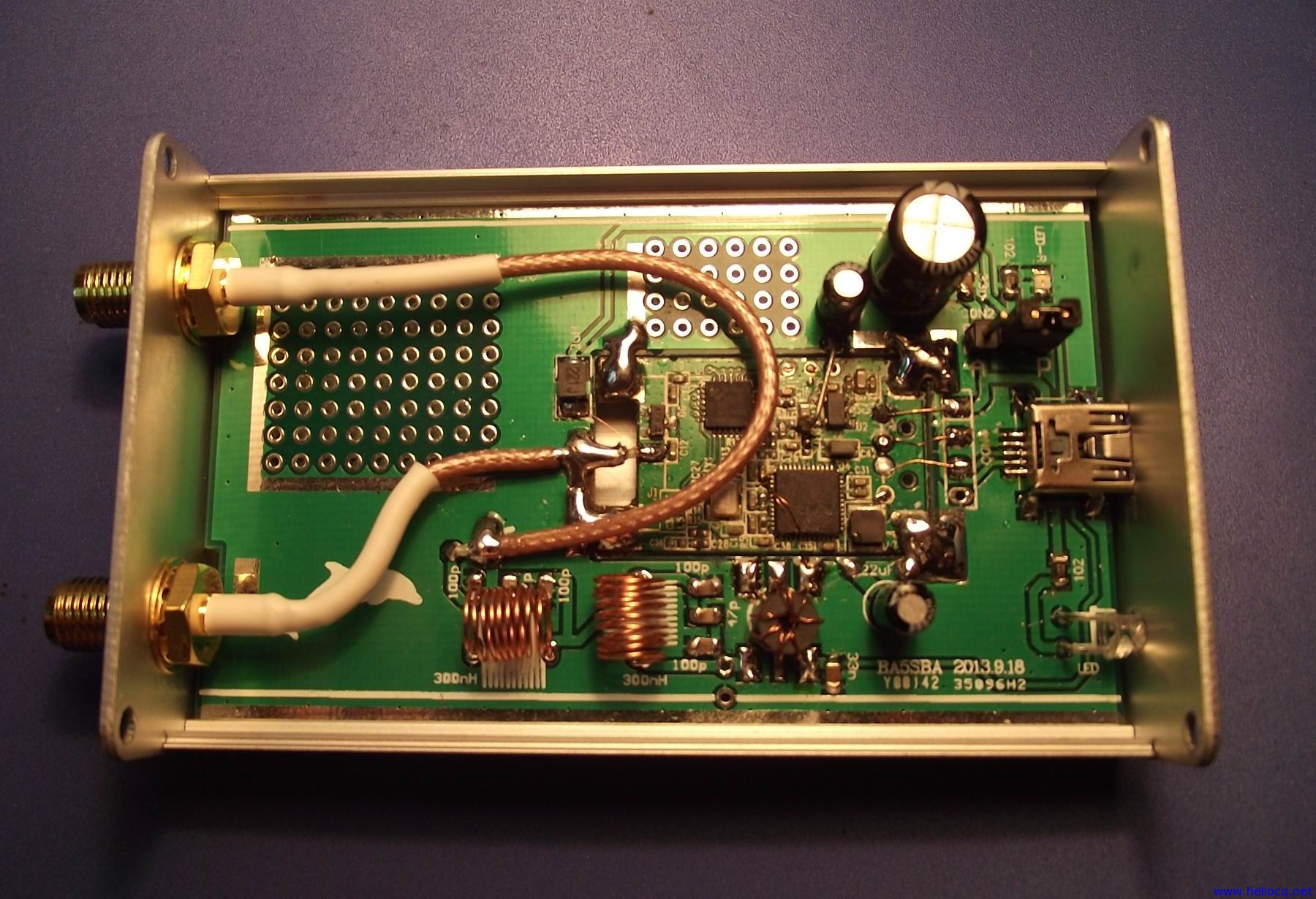
Il Collega Chavdar Levkov (LZ1AQ) presenta un circuito interessante che abbinato a un paio di antenne loop permette, a dir suo, ascolti interessanti. http://active-antenna.eu/


Il circuito, che vedendo le foto e leggendo le caratteristiche appare di ottima fattura, è venduto dall’Autore in Kit ha un prezzo accessibile e consiste come potrete constatare navigando sul sito di un circuito premontato con componenti smd. La curiosità che mi ha attratto del progetto è che il trasferimento dell’insieme antenna/preamplificatore e alimentazione del booster è fatto con cavo di rete schermato FTP (Foiled Twisted Pair) con connettori RJ-45, sicuramente condizione anomala rispetto ai nostri standard.


Queste le caratteristiche del circuito presentato:

General
Output impedance 50 Ohms, BNC connector on control board
Power supply(1) External, 13.8 V, =< 145 mA
Polarity protection & recoverable fuse are on the control board
Maximal output voltage(10) 6V p-p or 4.2 V p-p
Physical size 76 x 76 mm Amplifier board; 32mm x76mm Control board
Current amplifier with 1m diam. loop
Loop : diam. 1 m, 1 turn, conductor with 25 mm diameter, 2.4 uH
Antenna Factor Ka
(2) 2 dB meters-1 @ 10 MHz
(1 uV/m input signal will give 0.8 uV output voltage)
Ka Frequency response(2) 0.35 – 51 MHz; (within 3dB )
Usable frequency range (3) 0.02 – 55 MHz
MDS @ 10MHz (2) 0.7 uV/m , Noise bandwidth =1KHz
Output noise power at 10MHz(4,5) -113 dBm
1 dB output compression point(9) +19dBm (5.6 V p-p), equal to +125 dB(uV/m) at input
Second harmonic OIP2(7) +88dBm to +94dBm
Third harmonic OIP3(8) +41dBm to +42dBm
Voltage amplifier with dipole arms of 2 x 1 m
Antenna Factor Ka
(2) 2 dB meters-1 @ 10 MHz
(1 uV/m input signal will give 0.8 uV output voltage)
Ka Frequency response(2) 0.35 – 55 MHz; (within 3dB)
Usable frequency range (3) 0.02 – 55 MHz
MDS @ 10MHz (2) 0.25 uV/m, Noise bandwidth =1KHz
Output noise power at 10MHz (4,6) -118 dBm
1 dB output compression point(9) +19dBm (5.6 V p-p) equal to +125 dB(uV/m) at input
Second harmonic OIP2(7) +94dBm to +103dBm
Third harmonic OIP3(8) +40dBm to +42dBm


Sul sito  http://lz1aq.signacor.com/index.php troviamo serie di documenti  e progetti di Chavdar Levkov (LZ1AQ) qui altre info: http://www.qrz.com/db/LZ1AQ

Claudio Bianco.
http://laradioa360gradi.blogspot.it/


Radiorebus anch'io!


U.S. VLF Licenses granted to WH2XBA the 27 to 59 kHz - Licenze USA VLF concesse a WH2XBA 27 - 59 kHz


Sat Mar 1, 2014 9:05 am (PST) . Posted by: dl4yhf

Greetings all,
Licenses to transmit with up to (5 W ERP) (100mW ERP) have been granted to a number of radio amateurs in the U.S., in the 27 to 59 kHz range. Details (including the official license grant) have been posted to the the RSGB LF group. WH2XBA is a special 'experimental&#39; callsign in the US, actually used by multiple stations.

The stations are: 

WH2XBA/1 Bob W2ZM
WH2XBA/2 Warren K2ORS
WH2XBA/3 Jay W1VD
WH2XBA/4 Dex W4DEX
WH2XBA/5 Laurence KL1L
WH2XBA/6 /7 /8 etc etc James Plesa AA5BW

Initial tests by Bob (../1 in NY) on 29.499 kHz are on the way already, using QRSS120 (i.e. morse code with 120 seconds per "dot").
No details about phase coherence / frequency stability were given yet, but it may interesting for receivers in EU , too.
All the best,
Wolf DL4YHF .


Licenze USA VLF concessa a  WH2XBA    27 -  59 kHz
Saluti a tutti,
Licenze per trasmettere fino a 5 W ERP sono stati concessi a un numero di radioamatori negli Stati Uniti, frequenza da 27 a 59  kHz.  Dettagli (compresa la concessione di licenza ufficiale) sono state registrate al gruppo RSGB LF. WH2XBA è una speciale nominativo 'sperimentale' negli Stati Uniti, attualmente utilizzato da più stazioni.

Le stazioni sono:

WH2XBA / 1 Bob W2ZM
WH2XBA / 2 Warren K2ORS
WH2XBA / 3 Jay W1VD
WH2XBA / 4 Dex W4DEX
WH2XBA / 5 Laurence KL1L
WH2XBA / 6/7/8 etc etc James Plesa AA5BW

I test iniziali di Bob (.. / 1 in NY) sono  su 29,499 kHz, utilizzando QRSS120 (cioè morse code con 120 secondi per ogni "punto").

Wolf  DL4YHF.


About 27dB above noise in 43 uHz bandwidthhttp://abelian.org/vlf/tmp/29499_140302c.gif

and some sidebands are visible from the Morse.

A spectrogram in a wide bin width
http://abelian.org/vlf/tmp/29499_140302e.gif


and the signal is still visible even in 33.3 mHz bins where
you can begin to see some Morse.
http://abelian.org/vlf/tmp/29499_140302i.gif

I'm sure this signal will go a lot further east than UK, well
worth looking out for and a good test of rx sensitivity at an
unusually high frequency.

Bob is transmitting again tonight QRS180 or carrier with maybe
a frequency step for ID.

Thanks Wolf for the heads-up on this.

Paul Nicholson


Informazioni su QRSS :  http://www.arisandonato.org/index.php?option=com_content&view=article&id=71:iq2dp-esperienze-di-un-beacon-qrss-in-30-m&catid=25:ari-sdm&Itemid=55

RadioRebus n.58


73, Paolo R.