Recently I have bought five noise generators rated from 0.2 to 2000 MHz .
After a quick check I have realized that no one of them worked correctly or at all , all of them with common problems of designing and/or building , and other with also additional problems ( loss of components , bad soldering , cables broken during constructions ....
I supposed no one was really tested .
This was a start of the odissey .....
Checking the basic circuits is is made by a noise diode polarized with an LM317 with variable voltage with a trimmer , a 3 dB attenuator , a cascade of three monolitic amplifiers and another 3 dB attenuator .
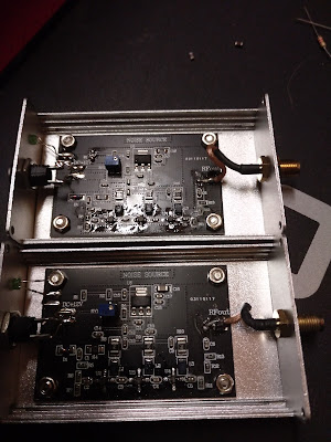
The first hardware generated noise , whilte the second didn't because the output cable was cut in the middle after having rolling it while screwing the SMA till the cable broke into two pieces !
What you see is the module after repair ( you can note that the cable is shorter because I used the cut part remaining connected to the SMA connector ) .
In the first module you can notice two capacitors missing on the right of the LM317 regulator .
This yelded errating instability during power up , I am sure due to autooscillations of the LM317 .
Anyway in both modules , the shape of the noise was very strange .
The fuzzy trace is the noise as it was at the beginning from 0 to 2.9 GHz with a Video Bandwidth of
1 MHz
The second clear trace is the mean of the noise made with a Video Bandwidth of 1 kHz after all the modifications I have made
This is the same , but also with the first trace ( without modifications ) , mean with a Video Bandwidth of 1 kHz
I noticed at first that the light of the LED was barely seen . The resistor for biasing was 10 kOhm . I changed with 1 kOhm and the light was better , but not as espected . Thinkink at a low quality LED usage , I leaved this for further investigation .
It took me some hours to understand the strange behaviour of the noise generator .
I didn't know what kind of diode was the one generating the noise . The voltage from the circuit of the LM317 was checked to be around 2V for both the circuit that with a resistor of 111 Ohm is enough to abruptly bias a normal diode .
Having a trimmer , at the end , with some reluctance , I tried to rotate it .
Nothings happens till a point where there was big instability on the noise and then a clean noise start to be seen as in the picture
The center trace is always the mean with a Video Bandwidth of 1 kHz
The " hole " in the middle of the first division is simply an artifact of the picture during Spectrum Analyzer scan .
The voltage generated fom the circuit was around 10 V with the trimmer full rotated .
The LED start to be very bright because was connected to this voltage , so I put again the 10 kOhm resistor to bias it .
The voltage across the diode was around 5V , so it looks to be a normal 5V Zener diode .
The strange noise we saw at the beginning was generated from the first monolitic amplifier and shaped from the retroaction between the cascade of the three ( Barkausen principle ) .
In some point we could see signals received from the circuits or excess on noise showing that at this frequency there is an effect as a Q multiplier ( Barkausen principle ) .
All this ceased as you see when the diode was polarized . Wrong diode mounted ? Who knows ? Surely bad trimming and no quality control check .
I went deeper into the LM317 circuit to understand while it changed so abruptly the voltage rotating the multiturn trimmer .
I don't know who designed this circuits . I can only say that it violate many good electronics practice and has nothing to do with the application circuits of the LM317 .
At the end I made modifications to follow the application circuits , but seen that at the end there was no variations from 7 to 10 V in the performances , I decided sinply to remove the LM 317 and mount a simple 78L08 monolitic regulator .
One of the five units was oscillating and apparently there was nothing to do as in the picture .
I started to remove and short circuit the inductances on the output of the monolitic amplifiers that sometimes generate this kind of problems with the self resonances , without results .
I had to change the inductances with SMD 100 Ohm resistors , but this decreased the performances and around the frequency of self oscillation still there was a strange response zone with an excess of gain .
At the end I started to introduce again the inductances , starting from the last amplifier and found that the self oscillation came from the first amplifier .After this and other tentative and struggling ( two couple of afternoons ...!) I noticed that probably the soldering of the monolitic amplifier on the two terminals of ground was too long od not perfect . Adding soldering alloy on both ground terminal returned the unit working as the other .
The odissey ended whan I noticed that the majority of the input connectors was not tighted and also some strong signals , like in the FM band entered through this path into the generated noise .
I suppressed this leakage with first two Ferrite impedance VK200 on both terminals and then I adopted two BLM41 SMD ferrites on all the units .
At this stage the odissey was ended and the generator can called a real " NOISE GENERATOR " .
Last measurement I made was the Return Loss at the output between 0 and 2000 MHz like in the picture : always better than 10 dB and always better than 20 dB till 200 MHz .
The trace is fuzzy due to the noise .
Following is the picture of one modified units ( starting with the VK200 impedance on the power supply ).
Will see in another publication , how same things could happen also to very simplest devices , in this case an SWR Bridge .
Luckily in this case the repairs was done simply with two contacts with the solder alloy to create strips non present on the circuit board .
Again this means that also this units was not tested at all !


Nessun commento:
Posta un commento
I commenti sono aperti a tutti e sono soggetti insindacabilmente a moderazione.
NON SARANNO PUBBLICATI COMMENTI SE PRIVI DI NOME E COGNOME ED EMAIL.
IL SOLO NOMINATIVO RADIOAMATORIALE NON SOSTITUISCE IL NOME E COGNOME RICHIESTO.
Grazie.
Nota. Solo i membri di questo blog possono postare un commento.